
Figure 1: The main commons showing speaker with A/V
Buxton, W. & Moran, T. (1990). EuroPARC's Integrated Interactive Intermedia Facility (iiif): Early Experience, In S. Gibbs & A.A. Verrijn-Stuart (Eds.). Multiuser interfaces and applications, Proceedings of the IFIP WG 8.4 Conference on Multi-user Interfaces and Applications, Heraklion, Crete. Amsterdam: Elsevier Science Publishers B.V. (North-Holland), 11-34.
EUROPARC'S INTEGRATED INTERACTIVE INTERMEDIA FACILITY (IIIF): EARLY EXPERIENCES
Bill BUXTON and Tom MORAN
Rank Xerox EuroPARC
61 Regent St.
Cambridge, CB2 1AB
United Kingdom
We present an introduction to the multimedia infrastructure of Rank Xerox's EuroPARC research facility. After a brief introduction to EuroPARC, the rationale and requirements of the infrastructure are summarized. We then provide an overview of the system, followed by a description of some specific examples that illustrate how the initial system was actually used. Finally, we present a fairly detailed description of the system's implementation.
ABSTRACT
The system discussed is an integration of distributed workstations and audio, video, and communications equipment. The intention of our presentation is to document our experience in such a way as to benefit others in the field. Hopefully new ideas will be stimulated from hearing about our excursion into this relatively uncharted territory, and others embarking upon research in this area may benefit from our experience.
EuroPARC's approach to studying HCI has two distinguishing features. First, it is concerned with technology in the context of groups and organizations more than the limited case of individual users. Consequently, issues such as collaborative work, meeting support, and the design and integration of technologies into physical and organizational environments are of special interest. Second, the lab is concerned with developing a better understanding of the process and methodology of design. It is especially concerned with the issues of effectively involving users in the design process in organizational settings.
In order to support these activities, a significant investment was made in the laboratory's infrastructure. A key part of this is what we call the integrated interactive intermedia facility (iiif). We believe that our motivation and experience in developing iiif may be of interest to others. Consequently, we offer the following documentation of our early experiences in setting up the facility and bringing it to use.
Before describing the system itself, some of its requirements can be outlined:
Group Support: A key demand of iiif was that it support group activities. In this regard, it was important that it provide facilities to support collaboration where participants are in the same physical location, or to help support telepresence where they are in physically distinct locations.Data Collection: If we were to study interaction, and in particular group interaction, it was important that the infrastructure support the collection of appropriate data. Since we wanted to pursue the interaction analysis methodology (for example, as described in Heath, 1986), this meant providing for the collection of audio, video and keystroke data.
Data Analysis: To be effective, tools to collect data must be accompanied by tools to support their analysis, such as described by Trigg (1989). Towards this end, iiif needed to support tools to index, annotate, edit, combine and view data of various forms, including audio and video.
Support of Multimedia Documents: We wanted to investigate the nature and the range of documents that could be supported in the workplace. In particular, we wanted to provide tools to support the exploration of documents, such as video, which have a temporal component. The system needed to support tools to save, retrieve, index, transmit and edit such temporal "documents."
Nonspeech Audio: In addition to video, audio played an important role in our research agenda. In particular, we wanted to be able to explore the use of nonspeech audio cues in supporting telepresence, collaborative work, and multimodal interfaces (Gaver, 1986; Buxton, 1989; Buxton, Gaver & Bly, 1990).
Envisionment: An emerging method of interest in user centred iterative design is what is we call envisionment. In the present context, this includes techniques such as the use of video to mock up designs, or the use of video to record actors, and mock environments in hypothetical scenarios. Such envisionment can be useful as the basis for discussing, communicating and exploring design ideas.
Formats and Standards: A basic but important requirement of the facility was that it take into account the reality of different video formats and standards. Being in the United Kingdom, we had to support the European PAL video standard. However, we also had to be able to support tapes in the North American NTSC standard, as well a play tapes of various formats.
This brief summary provides a flavour of the range of objectives
that the iiif had to meet. In the next section, we provide an overview
of our approach to meeting these needs.
Our belief that such a unified approach would work was based on the experience of the Mediaspace project at PARC (Stults, 1986, 1988; Harrison, Minneman, Stults & Weber, 1990). Mediaspace is like an in-house telephone exchange where connections are requested from each subscriber's workstation. However, instead of telephone calls, this exchange supports interconnections among multiple audio and video channels coming and going out of each "subscriber's" office.
Building on the Mediaspace model, we cabled the building such that every room was connected to a central location by a number of audio and video cables. At this central location, all of the cables were connected to a central switch, or "A/V exchange." This switch was computer controlled by a central server that could handle requests from any workstation in the building.
Figure 1: The main commons showing speaker with A/V
This room was designed for informal meetings. The A/V is fairly traditional, consisting of audio and video playback, a wall-sized whiteboard, and overhead projection.
This basic network formed the core of our system. In contrast to
the digital LAN that connected workstations, this star configured analogue
audio/video network was anything but tidy. While the technology wouldn't
scale up to a larger building, it was available, affordable and it worked.
Our interest was in usage, not technology. As long as we could hide the
technological inelegance of the implementation from the user, then it was
acceptable.
3.2. Meeting Support
We designed two main meeting rooms for EuroPARC. Each has a distinct
character. The commons, shown in Fig. 1 is open and casual, and intended
to support more informal meetings. The conference room, shown in Fig. 2,
lends itself to more formal meetings.
Both meeting rooms have double cabling to the central switch, and since a lot of our meetings involve various media, both have a range of A/V gear as standard equipment. Both have projection for 35mm and overhead slides, as well as facilities for video playback. The conference room is equipped with a rear-screen projector that can be used to display video or data from any type of computer in the building.
We designed the conference room, especially, as a laboratory for the study of meetings. Besides being instrumented, it is reconfigurable by virtue of its being constructed with a raised floor, flexible cabling, fax, phone, etc. Consequently, it can support meetings as diverse as electronic classrooms, COLAB-like meetings (Stefik, Foster, Bobrow, Kahn, Lanning & Suchman, 1987), and video conferencing.

Figure 2: The conference room
The conference room was designed to support a different type of meeting than the commons, shown in Fig. 1. It has rear-screen data, video and 35 mm slide projection. It can be used for presentations, and also as a videoconferencing room. The antenna-like object on the table is an omnidirectional microphone than can be used for teleconferencing. The room is designed to be easily reconfigurable in order to support other types of meetings, such as Colab-like computer mediated meetings.
The environment was also designed to allow us to explore meetings
and other interactions where the participants are not in the same physical
location. The objective here was to provide the means to explore our ability
to support telepresence.
The Mediaspace project and Xerox's corporate videoconferencing network (XTV) were our initial points of departure. For our initial efforts, we were happy to restrict our studies to in-house communication. As illustrated in Fig. 3, offices and meeting rooms were equipped with a video camera, microphone, loudspeaker and video monitor. Using their workstation, users could then instruct the server to interconnect the gear in different rooms to support the type of interactions desired. Examples of how this capability was used is illustrated by some of the examples below, such as SharedARK and Buttons.
The long-term plan is to link the central switch to the corporate XTV videoconferencing network, thereby affording us desk-top access to XTV nodes world-wide. While this is not yet in place, the infrastructure is designed to accommodate it if and when it becomes available. In the meantime, we have access to an XTV link (45 minutes away) and have performed some initial studies of linking desk-top units to the network.
Figure 3: An Office Node
All offices were cabled to a central audio/visual switch that functioned much like a private telephone exchange. The switch was controlled by a server that handled requests for resources from the user's local workstation. In the office, the audio and video lines terminate on a custom wall panel. A typical office would have a camera, monitor, microphone and speaker connected to iiif. Additional lines are available for connecting VCRS, an additional camera, or other A/V equipment.
3.3. Data Collection
Within the building, the A/V network and the in-office equipment illustrated
in Fig. 3 provide the primary tools for data collection. Using these resources,
data can be recorded in the central A/V suite (described below), or using
purpose-installed equipment in some other room. This is supplemented with
a range of field recording equipment (camcorders, portable VCRs and cameras)
that can be used off-site or in-house. Experimental sites can be easily
linked, and remote data recording and observation is facilitated. The description
of the SharedARK experiment, below, gives a good example of this.
3.4. The A/V Suite
One room in the lab was equipped with special A/V equipment. This was
termed the A/V Suite, and is shown in Fig. 4. The idea behind the suite
was that a number of functions could be met with a common facility. These
include use as the control room in experiments, special effects (such as
picture-in-a-picture), and the editing and analysis of audio and video
tape. For example, while one is for synthesis and the other for analysis,
the process of generating a video edit list is similar to the annotations
that an anthropologist makes during analysis.
While it looks like an edit suite, special concern was taken in the suite's design so that it could serve a broader function. In particular, the majority of the resources in the suite can be remotely controlled from other parts of the building, as well as from in the suite. Furthermore, using the A/V network and switch, signals can be routed between the A/V suite and other building locations, such as where a meeting is taking place or an experiment is being run.
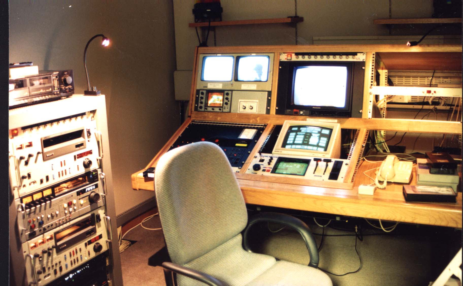
Figure 4: The A/V Suite.
Contains 3-machine computerized edit controller, 2 channel digital special effects unit, audio equipment, and test scope. The equipment can be operated both from within the suite and remotely from workstations in other rooms in the building. The suite is used for video editing, analysis, experiment control and special effects.
3.5. Data Analysis
Our initial idea was that the A/V suite, supplemented with appropriate
software, could provide the primary platform for analysis. That way researchers
could work in the suite, or from their office over the network.
In practice, this approach proved insufficient. First, the time lags involved in controlling the VCRs from a remote office meant that responsiveness was not acceptable in many cases. The reason for these delays was due to the overhead of the "chain of command," which went from the local workstation to the server to the VCR. To get around this, users always had the option to work in the A/V suite. However, those regularly involved in analysis wanted to work from their own offices whenever possible. This situation resulted in an on-going effort to evolve a "lighter weight" approach that would involve placing domestic quality VCRs in individuals' offices, and controlling them directly from the local workstation. Such an approach would compliment, rather than replace the existing configuration.
3.6. Video Mail/Documents
Video documents rapidly became an important form of communication within
the lab, and in communicating with our collaborators at PARC. From experience
gained early on (in cooperation with Sara Bly of PARC), it became clear
that quickly shot clips documenting meetings, talks and demonstrations
were a very potent means of communication. A courier service linking sites
equipped with a domestic video camcorder and playback machine provides
a video mail facility that is as effective as it is inexpensive.
By providing computer-controllable VCRs on-line that have auto-locate capability (using time code), iiif has the capability to provide on-line support for video mail and other video documents. This is an area of active research. Some preliminary experience in this direction is discussed in the examples below.
3.7. Nonspeech Audio
In keeping with our interest in making better use of human sensory
modalities, we have assembled a set of tools to support the investigation
of the uses of nonspeech audio. These tools include a range of computer
controllable audio equipment, such as synthesizers and samplers. [1]
The audio tools rely heavily on the MIDI protocol for computer control (IMA, 1983; Loy, 1985). Because of the need for fast response time, this equipment is not controlled by the central server. Rather, it is controlled directly by the researcher's local workstation.

Figure 5: Connectivity and desk-top telepresence
All of the rooms in the lab are interconnected via a computer controlled audio and video network. By equipping rooms with monitors, camera, loudspeakers and microphones, the basis for an in-house desk-top videoconferencing facility is provided. The figure illustrates a videoconference between two researchers. (Note the videotapes on the office "book" shelves. Video quickly becomes yet another form of of document used in everyday work.)
3.8. Standards etc.
In order to accommodate most of what might confront us, we purchased
at least one VCR in a range of different formats (U-Matic, VHS, and Betamax).
To accommodate different standards, most of our VCRs and virtually all
of our monitors are multistandard. Consequently, almost any tape can be
brought in, mounted, and played anywhere.
Finally, since multistandard machines are virtually unknown in North America, we acquired in-house standards conversion. While expensive, this is one of the most frequently used pieces of equipment.
The standards converter serves as an example to illustrate an important aspect of the "social" design that was part of the infrastructure. Right in the initial proposal, it was made clear that one function of our investment was as a "public service" that we could offer to help make links to the local community. For example, the standards converter was on loan to Cambridge University for three months before we had need of it. This helped establish good will and contacts in the video community that gave us access to expertise that supplemented that which we had in-house.
4.2. Buttons and Accessing the A/V Resources
The first package that gave easy access to the system was a set of
Buttons developed by a combination of Lennart Lövstrand, Alan MacLean
and Bill Gaver. The Buttons project itself (MacLean, Carter, Lövstrand
& Moran, 1990) was independent of iiif. However, its use in building
interfaces to iiif was a good example of the synergy that can result from
two projects leveraging off-of one another.
Figure 6: Buttons to make connections.
Buttons are a bit like soft function keys that can invoke procedures. They provide the user with a simple interface to perform a number of common transactions. They are relatively easy to program, simple to modify and tailor, and easy to distribute.Buttons are soft function keys that are easily tailored and easy to operate and share. Five buttons are illustrated in Fig. 6. Each one activates a different type of connection. These are:
"Pushing" one of these buttons causes a pop-up menu to appear. This
is illustrated in Fig. 7. In the example, the pop-up menu enables you to
select who you want to meet with.
Figure 7: Activating a button.
A pop-up menu appears when a button is selected thereby providing a list of alternative actions. In this case, the list contains the names of people with whom the activator may meet.
Buttons were easy to create, install and circulate (they can be
sent by email). Therefore, new ideas were easy to implement and test. This
rapidly gave rise to a number of insights. For example, the time-sensitive
nature of looking into someone's office became quickly apparent. Brief
glances (analogous to glancing through an open door) were acceptable, while
unconstrained watching was not. The initial server software did not support
temporal constraints on transactions. The buttons-based experience quickly
prompted an update.
4.3. Video Document Exchange: Video Mail and Videograms
From the early days of EuroPARC, video documents were an important
means of information exchange between PARC and EuroPARC. Largely initiated
by Sara Bly, tapes containing project information and other types of material
were sent back and forth by courier. Such videograms supported different
types of messages than other media and therefore supplemented, rather than
replaced, existing means of communication. For example, through video,
EuroPARC staff could "attend" demos at PARC, or observe project meetings.
Through videograms, the notion of telepresence was extended to asynchronous
as well as synchronous communication.
As we know from electronic vs traditional mail, the overhead of communication has strong influence on frequency an nature of messages. The overhead of videograms is still too high to be considered "email-like." As part of our research agenda, we are interested in investigating the situation where this is no longer true. In the meantime, videograms are still in use when a project demands high interaction or has special needs, or when users are motivated (by either early enthusiasm or technical aptitude). .
4.4. Remote and Shared Control of a Central Video Server
Five VCRs were connected to the central switch were controllable from
the A/V server. In order to utilize these machines from local offices,
such as to read or create video mail, Hugh Messenger built a prototype
application. The software takes the form of the virtual VCR control panel
illustrated in Fig. 8. Besides the standard functions, the panel permits
the choice of which VCR is to be controlled and permits the user to determine
the current location (in reference to its time code), and to cause it to
go to a specified location (also expressed in terms of time code).
Figure 8: Virtual VCR Control Panel.
The control panel permits the user to control a remote VCR from their local workstation. All common front panel controls are available in a familiar representation. The user can select which VCR is to be controlled. Multiple users may have such a panel active, thereby enabling shared control of a single VCR. This is used, for example, in cases where two or more people at different locations are viewing g a particular tape.
The button on the panel labelled MARK deserves special attention.
This enables the viewer to mark specific points on a tape during playback.
Each time the button is pressed, the system records the current location
of the tape, using time-code. Feedback is provided by way of a small form
that is attached to the bottom of the control panel. A number of these
forms, which we call tags, are illustrated in Fig. 9.
Each tag has fields that contain the start and end times of the marked section (expressed in time code), a text field in which annotations can appear, and a GOTO button that permits the viewer to navigate directly to the start of a marked section of the tape.
Using these video controls, more than one client workstation can simultaneously control a single VCR. Therefore, people at remote sites can watch the same tape, have voice communications among themselves to discuss it while it is playing, and anyone of them is able to stop, pause, rewind, etc. the tape themselves, since each may have a virtual control panel for the VCR on their own workstation.
Figure 9: Marking and tagging locations on a video tape.
Tapes can be indexed using the MARK function. This generates a form which contains the location, annotation, and controls to access the indexed location.
4.5. Reciprocal Video Tunnels
One of the problems that is quickly noticed in conventional videoconferencing
is the lack of eye contact. Furthermore, some people, expressed dissatisfaction
with video links in that it was difficult to tell if anyone was looking
at you.
Figure 10: The Reciprocal Video Tunnel.
Through the combination of a mirror and half silvered mirror, there appears to be direct eye-to-eye contact. The mirrors effectively place the camera right in the line of sight. A close approximation to reciprocal eye contact can be obtained if both parties are using such an arrangement.
To address these issues, Randall Smith and William Newman started
to explore ways in which they could configure their monitors and cameras.
The result was an arrangement that employed a technique borrowed from broadcast
teleprompters. The technique is shown diagrammatically in Fig. 10.
Effectively, the arrangement places the camera optics in line with the monitor. This is done using mirrors. The mirror in front of the monitor is half silvered. Consequently it does not obstruct the view of the monitor, yet still provides the reflective function for the camera.
A number of boxes using this approach were constructed. These were called video tunnels. Fig. 11 shows a desk with a workstation and a video tunnel. Note that the camera is hidden inside the box.
Figure 11: A Video Tunnel in Use
The figure shows the desk of Randall Smith, holding his workstation (left screen) and one of the Video Tunnels (right screen).
The use of such teleprompter-like technology to obtain eye contact
has been used by others (Acker & Levitt, 1987); however experience
with them is not widespread. The technique has a number of interesting
properties:
The video connections of the experiment are shown. The white regions indicate the separate rooms. Equipment in subjects rooms are connected to the network via the local wall panel. All signal routing is controlled by the central A/V switch. The A/V suite is used as control. The PIP (picture in a picture)unit combines the four channels of video into one frame, one channel of video per quadrant (as shown in the next figure).The only non-standard part of the physical configuration are the two extra cameras used to view the subjects' screens. All connections are made by software.
4.6. SharedARK Experiments
One of the first and most demanding uses of the system was a series
of experiments to explore joint problem solving at a distance. The experiments
used the SharedARK environment in combination with a pair of video tunnels
(Smith, O'Shea, O'Malley, Scanlon & Taylor, 1990).
The video component of the A/V configuration used in the experiments is shown in Fig. 12. (The audio set up was similar.) In the experiments the A/V suite was used as the control room. Subjects were placed in separate rooms. Each room has a standard A/V node set-up, with the camera/monitor pair for each taking the form of a reciprocal video tunnel. An additional camera was installed to capture an over-the-shoulder shot of each subject's computer monitor. The signal from these cameras were routed to the the A/V suite via the room's local wall panel.
All audio and video signals were routed to the control room under software control (with the video tunnel signals also sent between subjects to maintain the link). In addition, voice communication was provided among the control room and both subjects, thereby permitting the experimenter to monitor what was going on and intervene if required. Finally, all four channels of video and two channels of audio were combined and recorded in a synchronized manner on a single tape (one video channel per quadrant of the frame). The video channels were combined using the picture-in-a-picture capability of the A/V suite. A sample frame from the resulting video is shown in Fig. 13.
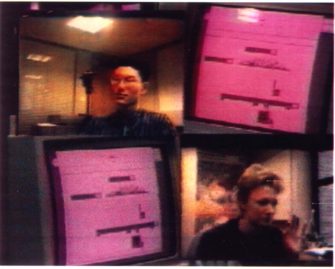
Figure 13: Experiment Monitoring
The SharedARK experiment involved four channels of video, as illustrated in the previous figure. These were combined onto one channel for analysis. The top right quadrant show's the top left subject's screen. The bottom left quadrant shows the bottom right subject's screen. The subject's video monitor showed a full-screen view of the other subject, only.
The only nonstandard component of the set-up were the two "over
the shoulder" cameras. All connections were made through software, and
once defined, the entire experimental configuration could be set-up in
about twenty minutes!
4.7. Nonspeech Audio in Collaborative Work
In later experiments, nonspeech audio was added to the SharedARK setup.
This work was done in conjunction with Bill Gaver (Gaver & Smith, 1990).
In this case, Gaver designed distinctive auditory icons (earcons) for each
class of user action. These earcons provided a form of auditory "footprint"
which provided auditory feedback on their own and other's actions. (The
usage here can be thought of much like the case where you are working on
some foreground task, and hear someone in the background making tea.) When
two people were working together (but at a distance), the other person's
sounds were made to sound more "distant" than those made by oneself. Consequently,
sound conveyed both action type and causal agent.
Our approach to using sound was ecological, where we tried to use sounds in an everyday way to convey a sense of the state of the building and activities within it. A concrete example of this is the use of sound in the glance operation, seen earlier in the discussion of Buttons.
Our first approach to the system was that video links should be reciprocal: if you can see me, I should be able to see you. However, if I am having a meeting in my office, your appearance on my monitor could be an intrusion similar to your walking in and interrupting the meeting. An alternative approach was afforded by the use of sound. In this case, when you glance into my office, I hear the nonintrusive sound of a door squeaking, and when your glance terminates, I hear the sound of a door gently closing. In addition, optional cues are available to identify who had done the glancing.
Our exploration of the use of sound to support copresence and other activities is ongoing. These brief examples give a sense of our direction. Of central importance is the power that is afforded this exploration by the combination of the audio distribution network, sound equipment and server software provided by iiif.
We had no vested interest in developing technologies, per se. Our interest was in usage, and having usage drive the engineering rather than the other way around. Hence, we wanted to get up to speed as quickly as possible with whatever technology that would enable us to do so. While obsolete technically, the technology that we chose worked, was understandable, and was available. In short, we wanted to learn to do smart things with stupid technology today, rather than wait and do stupid things with smart technology tomorrow.
As long as the technologies that we used could (in classic Wizard of Oz tradition) emulate the behaviour of future systems to the user, it made no difference how it was actually implemented (assuming the implementation was transparent).
5.2. Rules of Thumb
Before going into details, there were a few rules of thumb which guided
much of the equipment acquisition.
5.3 . The Basic Network
The basic architecture of the A/V distribution system is illustrated
in Fig. 14. Here it is seen that the system is connected in a star configuration.
The hub of the star is is the central A/V switch, or "exchange".
Cables connect the hub to about 25 offices, 3 commons rooms, and the conference room. There is one cable per video signal. No broadband or multiplexing is used. The standard setup has 4 baseband video lines and 6 audio lines running between each location and the switch. These are unidirectional, and are split evenly between directions (video: 2 coming / 2 going; audio: 3 coming / 3 going). Some rooms, such as the conference room and the A/V suite have extra cabling. In total, the hub has 77 incoming and 77 outgoing video lines, and 140 incoming and 140 outgoing audio lines.
Figure 14: The Basic A/V Distribution Configuration
Audio and video signals are distributed in a star topology between a central hub to user nodes. Normally there are 4 video lines (2 in each direction) and 6 audio lines (3 in each direction) between each node and the hub. There are 32 office nodes connected to the central hub switch.
All audio and video cables are distributed in the ceiling in the
same cable troughs as the telephone lines, mains power lines, and ethernet
cables. To avoid interference, the audio and video cables were kept as
far as possible from the others. Furthermore, the best quality broadcast
cable available (i.e., the best shielded) was used for video. Audio lines
are all shielded, balanced, and low impedance. Despite long cable runs,
extending over the three stories of the building, no problems of cross
talk, interference, or grounding loops were encountered.
No timing delays, amplifiers, or equalizers were used on the video lines. The video signal quality is not broadcast quality, but is more-or-less acceptable. (We are currently investigating the acquisition of a small set of variable video delays and equalizers that can be patched into video circuits in cases where the highest possible signal quality is required. The economics of doing this for all lines would have been economically prohibitive.)
5.4. The Hub Switch
The A/V switch at the hub of the system is not a single cross-bar.
While ideal, cross-bar switches of that capacity would have been too expensive.
Rather, the approach taken was to employ a number of smaller cross-bars,
and provide some communications capacity among them.
For our purposes, the switches used were made by Akai. (These switches
were used for two main reasons: the worked and they were nearly a factor
of 10 less expensive than anything else available that they could be compared
to.)
Two different switches were used in the system: the D2000 which has 16x16 audio and 16x16 video, and the D3200, which has 32x32 audio (no video). There are currently 7 D2000 switches and 3 D3200 switches. Some inputs and outputs from each switch are used to interconnect switches rather than to communicate to the user nodes. With the D2000 switches, this represents about 1/3 of the I/O capacity: 5 inputs and outputs for each of audio and video.
Figure 15: Video switch topology.
Shows 11 inputs and outputs connecting each switch to user nodes and 5 inputs and outputs used for switch interconnect. The daisey-chained approach to bridging switches was intended as temporary, to be replaced by additional interbridge switches, as in standard telephone switching techniques.
The topology of the initial interconnect of the switches is a trivial
daisy chain. The video interconnect is illustrated in Fig.15. This configuration
is clearly inadequate except for initial testing and debugging, since there
is too much potential for blocking and knock-on effects. The plan was to
provide additional switches to provide an interbridge among the existing
switches. This would use a slight variation on standard telephone switch
topologies (Buxton, 1989).
5.5. Control and the A/V Server
The Akai switches normally come with a dedicated controller. This is,
in fact, a black box computer. For our purposes, this controller was inadequate.
Among other things, it restricted control to four switches, less than half
the number that we needed.
Through the efforts of Mark Wilson of the BBC (one of the many collaborators who helped us bring the system to fruition), we found out that electronically, the protocol used between the Akai controller and the switches was MIDI (IMA, 1983). Consequently, all that was required to control the switch from another computer was a MIDI interface, specially made-up cables, and the logical control protocol (which we were finally able to obtain from Akai UK).
Through this circuitous route, we were able to have all of the switches controlled from a single computer of our own choice. This was a Sun workstation, which now fulfilled the role of A/V server. Since the server sat on the network, the hardware was now in place to permit the switch to be controlled, via the server, from remote clients running on end users' workstations. The combined control and signal topology is illustrated in Fig. 16.
5.6. Server Software
The basic tools provided by the infrastructure consisted of a set of
base transactions that could be performed by the server at the request
of a client. Transactions were expressed in the form of remote procedure
calls (RPCs). These can be initiated from any machine on the network, regardless
of type or environment, as long as they can support TCP/IP protocols. Hence,
control of the system could be effected from a range of different computers.
Figure 16: Signal and control topology.
Audio and video signals are distributed in a star topology from a central hub (thick lines). Control is distributed over the LAN, with client processes on the end user's machines communicating with the A/V server. A/V server controls hub switch from RS-232 port. Clients communicate with server using remote procedure calls (RPCs). LAN is Ethernet and Appletalk bridged. Machines connected to either can issue RPCs to server using TCP/IP protocol. Hence, server is largely computer, network and environment independent.
Without going into to great detail, there were a few basic concepts
that guided the design of the server software. One is the notion of ownership.
The server administers all resources. When resources are requested by a
client, they are delivered if available and become unavailable to others
without the new owner's permission. If resources are unavailable, the server
can report on their status.
There are a few important consequences of this. First, some degree of privacy becomes available. Secondly, one can grab some resources, and then have some degree of a "brick wall" around them while they perform experiments.
One thing that we did wrong with the software was have a blocking mechanism during service. The original concept was that RPCs would be serviced quickly. Consequently, while one was being serviced, others would be blocked. This made the code easier, but the resulting contention was more serious than expected, especially when performing real-time control of devices.
An important aspect of the server software was that the clients never addressed their requests in terms of the switch itself (i.e., its I/O ports, for example). All transactions from clients are expressed in terms of point-to-point connections. One specifies who or what you want to connect to, rather than the route through the switches required to get there. This is important for two reasons:
In putting the system together, more than 2,000 audio and video connections were made. To make the system maintainable, we did two things. First, every individual cable has a unique identification number, which appears on a colour encoded number at each end. Furthermore, every connection is entered into a data base (an Excel spreadsheet), with its number, signal type (audio/video/control), direction of flow (sink/source), name of device it is connected to (eg., "JVC 6200 VCR#1"), and the specific connection of that device (eg., "audio output 1").
The resulting data base documents the complete configuration. It includes
macros to check for errors such as "3 ended cables", sinks connected to
sinks, etc. Most important, the database can be read by the server. When
the configuration is changed, the database is updated and read by the server.
The server then services requests for resources using its internal representation
of the current configuration and a general path-finding mechanism. Since
all connections requested by clients are by reference (i.e., device rather
than the specific switch port to which that device is connected), all such
changes are transparent to the user and user applications - a good thing
in any evolving system.
This software was written by Tom Milligan, with help from Hugh Messenger
and Lennart Lövstrand.
5.7. User Nodes
User nodes normally have 4 video lines and 6 audio lines between them
and the hub switch. The standard configuration is for each user node to
be equipped with the following:
Different examples of a user nodes are illustrated in Figs. 5, 11
and 17.
Although 32 locations in the building were cabled as nodes, we initially purchased equipment to equip only 10 of them. This was in order to enable us to explore different types of cameras and monitors, for example, before making the full investment.
Our experience has brought a number of issues to light. For example, size of monitor, position of camera and monitor, response time of control software, and lighting have a strong effect on usage. Furthermore, the importance of audio quality in conveying a sense of telepresence cannot be over emphasized. Consequently, microphone and speaker selection and placement is critical, and great care must be taken to control ambient noise from disk drives or fans, which can greatly degrade the quality of usage.
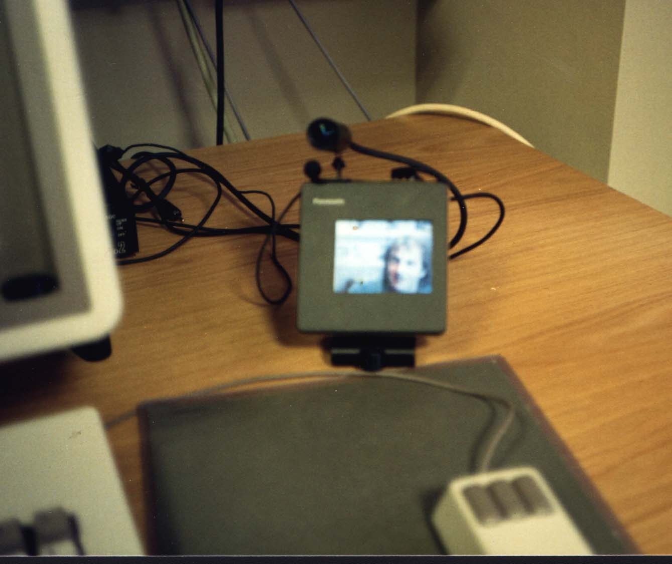
Figure 17: A Miniature User Node.
Typically users employ different configurations as well as different types of monitors, cameras, etc. One aspect of the research is to develop an understanding of the implications of such variations. Two configurations have been seen in previous figures. The example in this figure shows a miniature system which occupies minimal space on the desk-top. Because of its size, the angle from the eye to the camera and monitor is sufficiently small that eye contact can be established without the need to revert to the complexity of the video tunnel. On the other hand, while adequate for "talking heads" type conferencing, the monitor is not large enough to view videotapes in detail. Gaining experience and developing an understanding of these types of trade-offs was a major objective in our work.
5.8. Avoiding Adaptoritis: The Wall Panels
One of the strongest messages conveyed to us from Steve Harrison of
the Mediaspace group was the fact that every device has a different type
of connector, and the availability of the suitable adaptor was inversely
proportional to the square of its need.
To minimize some of these problems, we took special care in designing a standard wall panel, illustrated in Fig. 18, to terminate the cables in each office.
The main purpose of the panel is to handle some of the problems associated with connectors and the vagaries of audio. The panel can accommodate almost every signal type and connector type that can reasonably be expected. It can handle signals that are balanced and unbalanced, high or low impedance, mike or line level, and 1/4" phone, phono (RCA) or XLR connectors. Regardless of input or output level, type, or connector, the panel makes sure that all audio signal traffic between it and the hub switch is low impedance balanced line level.
The unit has a variable gain mike preamp selectable on each input, and one input has a voice activated switch which turns off the local speakers whenever (and for as long as) the input is above a user settable threshold. This helps prevent audio feedback.
Even more than cameras, microphones can be an objectionable source for invasion of privacy. For example, "ear dropping" on a private conversation with a microphone is far more serious than "eye dropping" with a camera.
This in itself is not news. To handle this, out initial approach was two-pronged: not to have microphones in pubic spaces, and to give users access to manual on/off switches on the microphones in their private spaces.
Figure 18: Wall Panel, Mk II.
The wall panel is the interface between the cables to the hub switch and the cables to the equipment in the user's node. Redundant audio connectors of different types are provided, as well as phantom power for condenser microphones, mike preamps, a voice activated switch to avoid feedback, and other features.
Nevertheless, users still continually forgot to turn their mikes
off. Furthermore, when visitors were in an office, they had no way of knowing
the microphone status. Consequently, in the second version of the wall
panel, we addressed this issue as follows. First, we added the capacity
for a foot-pedal operated on/off switch for the microphone (such as used
for the sustain function of an electronic piano). When the pedal is used,
audio is passed through the microphone preamp only when the pedal is depressed.
Hence, the user must take a deliberate and inherently temporary action
to activate the mike. Secondly, there is a connector that permits a light
to be attached so that a red "recording" indicator can be easily connected.
Figure 19: Central VCR Service
Five VCRs are under control of the A/V server. The full functionality of these machines, including time-code functions such as automatic locate, are accessible from client machines, over the LAN. Audio and video inputs and outputs of the VCRs are connected to the central switch, and can therefore be accessed from individual nodes via their wall panels.
5.9. Remote VCR Service
As described earlier, there are a number of VCRs available for use
from the client workstations. Two are permanently on line, and three are
switchable between being on-line or being under the control of the computerized
editor in the A/V suite.
The audio and video outputs of these VCRs are connected to the hub switch. Their functionality is controlled by the A/V server software using RPCs from the client. Each machine can be individually addressed. Functions available include autolocate, since the interface handles the time code on the VCR being controlled.
Control is effected through the use of a Videomedia VME "video LAN", or VLAN. This permits up to 16 VCRs to be controlled from one RS232 port. The logical relationship of these VCRs to the overall system is illustrated in Fig. 19.
5.10. The A/V Suite
The A/V suite is a special node, in that it has a great deal of specialized
equipment. This room presented one of the largest design challenges of
the system: could one room meet the needs of the video literate "power
user" and still be usable by the novice.
Based on our experience, the answer is yes, but just. To do so requires careful selection of equipment, its layout and presentation, and training.
We did a few things to make the room manageable. First, any equipment not needing hands-on attention was moved to the server room. Second, we concentrated on computerized reconfigurable equipment. As a result, the user can go through an initial procedure and be reasonably confident that the equipment is in a standard "default" condition. This includes our placing a small red marker to indicate the default position for virtually every manually settable switch.
Finally, we spent a fair bit of money on furniture to house the equipment. This not only helps the ergonomics, but hides a great deal of cabling and complexity.
With the emergence of inexpensive consumer-level video editing equipment, it is likely that we would now take a different approach to this part of the system. A centralized approach to video editing is in conflict with the notion that video is just another form of document. If video is a document, then we should be able to perform transactions on it from our everyday workstation. As with text and graphics, this implies the ability to author, read, edit, annotate, index, transmit, save and retrieve such documents. It also means providing the ability to process hybrid documents. Just as we can now cut and paste between graphics and text processors, we should be able to easily include audio and video elements. While a central A/V suite has many uses, we feel that many of the services that it is intended to provide are now technically and economically feasible to integrate into the local workstation, thereby providing a far richer environment for exploring the use of these new enriched documents.
Following the path that we did came at a price. Based on how it has been used, despite its problems, we believe that it was worthwhile. We also believe that many of the services that it provides us in supporting our work will eventually become fairly common.
We hope that this sharing of our experience will help others benefit from what we did right, and avoid some of the pitfalls where we stumbled.
We also gratefully acknowledge the help, advice, support and encouragement that came from our counterparts at PARC, especially Mark Chow and the Mediaspace team, including Steve Harrison, Sara Bly, Karen Weber, Scott Minneman and Bob Stults. Without them, probably none of this would have happened.
Bill Gaver and Randall Smith made an important contribution as early users who provided valuable feedback and experience. Our colleagues at Rank Xerox's Welwyn Garden City site, especially Bob Wildsmith provided a lot of technical help and support in working with the satellite video conferencing link. Lucy Suchman and Gitte Jordan provided valuable input concerning the use of video in analysis.
Finally, we would like to acknowledge the help of Mark Wilson and Brian Hodgson of the BBC's Radiophonic Workshop who helped so much in reverse engineering the control interface to the Akai switches.
Buxton, W. (1989). Upgrading the A/V Switch Topology. Unpublished report. Cambridge: Rank Xerox EuroPARC.
Buxton, W. (1989). Introduction to this special issue on non-speech audio. Human Computer Interaction, 4(1), 1-9.
Buxton, W., Gaver, W. & Bly, S. (1990). Introduction to the Use of Nonspeech Audio in User Interfaces. CHI '90 Tutorial Notes. New York: ACM/SIGCHI.
Gaver, W. (1986). Auditory icons: Using sound in computer interfaces. Human-Computer Interaction. 2, 167 - 177.
Gaver, W. & Smith, R. (1990). Auditory icons in large-scale collaborative environments. Unpublished manuscript. Cambridge: Rank Xerox EuroPARC.
Harrison, S., Minneman, S., Stults, B. & Weber, K. (1990). Video: a design medium. SIGCHI Bulletin, 21(3), 86-90.
Heath, C. (1986). Body movement and speech in medical interaction. Cambridge, UK: Cambridge University Press.
IMA (1983). MIDI musical instrument digital interface specification 1.0. North Hollywood, CA: IMA. (Available from IMA, 11857 Hartsook Street, North Hollywood, CA, 91607, USA.)
Loy, G. (1985). Musicians make a standard: the MIDI phenomenon. Computer Music Journal, 9(4), 8 - 26.
MacLean, A., Carter, K., Lövstrand, L. & Moran, T. (1990). User-tailorable systems: pressing the issues with buttons. Proceedings of the ACM/SIGCHI Conference on Human Factors in Computing Systems, CHI '90, 175-182.
Moran, T. & Anderson, R. (1990). The Working environment as a paradigm for CSCW. To appear in the Proceedings of the the 1990 Conference on Computer Supported Cooperative Work, Los Angeles.
Smith, R., O'Shea, T., O"Malley, C., Scanlon, E. & Taylor, J. (1990). Preliminary experiments with a distributed multi-media, problem solving environment. Unpublished manuscript. Cambridge: Rank Xerox EuroPARC.
Stefik, M., Foster, G., Bobrow, D., Kahn, K., Lanning, S. & Suchman, L. (1987). Beyond the chalkboard: computer support for collaboration and problem solving in meetings. Communications of the ACM, 30(1), 32-47.
Stults, R. (1986). Media Space. Systems Concepts Lab Technical Report. Palo Alto, CA: Xerox PARC.
Stults, R. (1988). Experimental uses of video to support design activities. Technical Report SSL-89-19. Palo Alto, CA: Xerox PARC.
Trigg, R. (1989). Computer support for transcribing recorded activity.
SIGCHI Bulletin, 21(2), 72-74.
Notes:
[1 ] A Sampler is effectively a modular
digital audio recorder/player. One can store a number of short sounds in
the device, and then play them back on demand under computer control. As
its name suggests, a synthesizer generates synthetic sounds. In contrast,
samplers are well suited to playing back natural sounds, thereby expanding
the sonic palette available in our research.