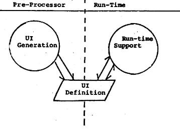
Fig. 1. Main Modules of a typical
UIMS
Tanner, P.P. & Buxton, W. (1985). Some Issues in Future User Interface
Management System (UIMS) Development. In Pfaff, G.
(Ed.), User Interface Management Systems,
Berlin: Springer Verlag, 67- 79.
|
National Research Council of Canada, Ottawa,
Ontario, Canada
|
Computer Systems Research Institute
|
UIMS's have grown out of an emerging recognition that designing consistently good user interfaces is as difficult as it is important. Virtually all work to date has been based on a few common premises:
The objectives of such systems go even further, however. By isolating the UI as a separate module from the application and providing adequate tools, it is argued that the design of the UI can be undertaken by a specialist, who is not necessarily a programmer (Buxton et al 1982; Feldman & Rodgers 1982; Foley 1982). Finally, UIMS's facilitate the implementation of UI's that utilize asyncronous I/0. Because of system dependencies, this important mode of interaction is typically difficult for the application programmer to implement.
Existing UIMS's, based on the ideas outlined above, have gone a long way towards meeting their objectives. However; in examining the roots of some of their short-comings, and in planning for the next generation UIMS, certain critical questions arise. For example:
Our prime objective is to encourage research
into each of these issues. The rest of this paper will utilize existing
UIMS's to discuss them in further detail.
There is conflicting use of the tern user
interface manager. It has been used to refer to a person who manages
a UIMS, and to the UIMS itself. For our purposes, the term will refer to
the person, and UIMS will be used to refer to the system.
From this simple model, already several
issues arise. For example, it can be seen that the structure of the UI
Definition File can have a great influence on both the pre-processor and
run-time modules. If it is a regular table, it is relatively easy to build
tools to generate and edit it. On the other hand, there are problems of
efficiency in implementing large tabledriven systems. Perhaps an even more
important issue is the model's assumption that the
Fig. 1. Main Modules of a typical
UIMS
Interaction definition takes place previous
to run-time, and probably before compile time. An alternative approach
would be for the system to be structured such that the UI definition table
could be altered at run-time. This is an alternative that will be discussed
In a later part of this paper.
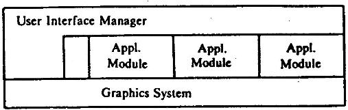
Fig. 2. Structure of External
Control UIMS (from Thomas, Hamlin, et al 1982)
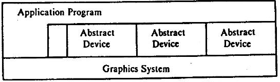
Fig. 3. Structure of Internal
Control UIMS (from Thomas, Hamlin, et al 1982)
Figure 3 illustrates what they have termed an internal control UIMS. In this case, the application program is in charge of the flow of control within the package. It requests various abstract devices (e.g. choice, 2D valuator) when they are required by the application. A .third model was suggested at the Seeheim workshop. This is a concurrent model, where the UIMS and application run in parallel.
The principal problem with any of these models is that it is not always clear what falls on what side of the line between the application and the UIMS. For example, is semantic feedback a function to be performed by the UIMS or the application package?2 The UIMS cannot perform semantic feedback when this requires knowledge and manipulation of an application data base. The application cannot perform semantic feedback when such feedback is a function of the particular interaction design.
We have had examples of both cases in our experience with the ACTION package.3 When used to manipulate control points in sculpted surface generation, ACTION was incapable of generating the required surfaces. This has to be done by the application program. On the other hand, Action was also used to vary parameters controlling a strip-mining simulation. The original application code had been written without any graphics input or output. By peeking into the data base of the application, ACTION was able to plot the position of trucks and status of shovels in the mine. Thus, this system included a module that crossed the boundary between the UIMS and the application program. Perhaps in future, a finer distinction must be drawn between two classes of graphics: that to be handled by the UIMS and that to be handled by the application. In this case, however, an unambiguous means of assigning responsibilities must be developed which constrains the application by removing some 'direct' control from it.
In many applications, an appropriate way of specifying the data to be operated upon is to draw a circle around it on the screen, or "collect" it by successive "pick" operations. As Olsen and Dempsey (1983) point out, however, this transaction embodies one of the ten unsolved problems of computer graphics, as identified by Sutherland (1966). The pick operation just returns a segment number. How can a UIMS, with no semantic knowledge, possibly know what was intended by the transaction, based on the segment numbers alone? Clearly the UIMS needs some semantic knowledge to enable it to map the graphical information into the user's data model.
Garrett and Foley (1982) present one approach to the pick problem using data base techniques. However, the approach suffers from the fact that it assumes a particular data model, and therefore causes the UIMS to lose some of its desired generality. Also, such an approach will often be too slow for good interaction. We have, therefore, conflicting demands being made by our desire for speed and generality.
Another approach is to have the application supply a "pick service". This, however, must be rewritten for each application, and would be a non-trivial task if it must be able to handle "collected" or "encircled" items, rather than individual picks. Regardless of the approach, the issue must be dealt with. Otherwise, existing UIMS systems will be prejudiced against "chalk-talk" type dialogues which have proven their use, as illustrated in Buxton, Fiume, Hill, Lee & Woo (1983).
There are other areas where problems occur
in attempting to separate the UI from the semantic component. One example
concerns how the system handles setting and assuming default values. This
has a great influence on the UI, and yet it requires a deep understanding
of the semantic component to set up. How a UIMS would handle the integration
of a spelling checker (Durham, Lamb & Saxe 1983) into a word processor's
UI would be another example. Problems of this class will become more pronounced
with the advent of knowledge-based, or "expert" systems. Here we see the
need for a convergence of UIMS research with that of Al, as already begun
in Ball and Hayes (1980) and Shell (1983).
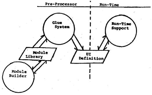
Fig. 4. UIMS with Glue System and' Module Builder
MENULAY (Buxton et al 1983) and ACTION (Tanner & Evans 1979) are examples of systems which can be characterized as glue systems. They are tools that permit interactive dialogues to be constructed by using prepackaged modules. These modules, or "dialogue cells", are interactively selected from a library by the interaction programmer. The role of the UIMS, therefore, is to provide access to this library and provide the administrative support required to bind these modules to each other and to the application. The power and range of such systems is largely a function of the range and power of this library. What these systems provide, is a good environment for working on the dialogue at a very high level with minimum complexity.
In contrast, TIGER (Kasik 1982) and SYNGRAPH (Olsen & Dempsey 1983) are examples of systems that are not as well suited to dealing with the "presentation" level of the interface. Where their special strength lies is in specifying and implementing the low level details of the dialogue structure. An example would be defining the interaction modules used by the glue systems. This power derives from their providing a special language for defining interaction dialogues. More training is required to use such systems - one has to learn a new programming language. However, such systems are quite general. The interaction programmer is not restricted to the set of interactive techniques that some user interface manager has provided in some library. Rather, tools to create one's own library are provided.
What is important to note is that the glue
systems and module builders can, and probably should, co-exist in a complimentary
fashion.4 In this model, which is shown
in Fig. 4, we see that the pre-processor is,' partitioned into two main
modules which communicate through a dialogue cell "module library". Simply,
the glue system is used to patch together dialogue cells created by the
module builder. (The glue system may be, as in MENULAY, implemented from
the low level modules in the module library.) Approaching things from this
perspective, and making this distinction explicit, has the advantage that
those tasks which should be done by an interaction specialist, who is not
a programmer, are isolated in the glue system. Those functions that require
a more specialized knowledge of programming concepts are isolated in the
module builder.
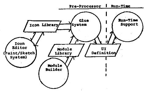
Fig. 5. Layered System with
icon Generator and Library
The layering of the system can be extended
one more step. Designing the presentation level of the UI includes the
design and layout of icons (which may be used as light buttons and tracking
symbols), and other graphics segments used for lexical and semantic feedback.
The layout function is naturally handled by the glue system. However, like
the design of interaction modules, the design of icons requires a special
environment. This module would store graphics in a standard format in a
special library, which would be accessed by the glue system (as shown in
Fig. 5). One implication of this structure is that a standard format for
the graphics exists (such as GKS metafiles).
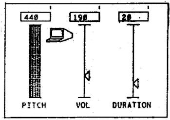
Fig. 6. Graphic Potentiometer
Module
We tend to use computers as if we had no
feet, only one hand, and no ears. However, our operation of other machinery,
such as automobiles or sewing machines, illustrates the complex interactions
of which we are capable. A major objective of UIMS design should be to
serve as a catalyst in realizing this potential.
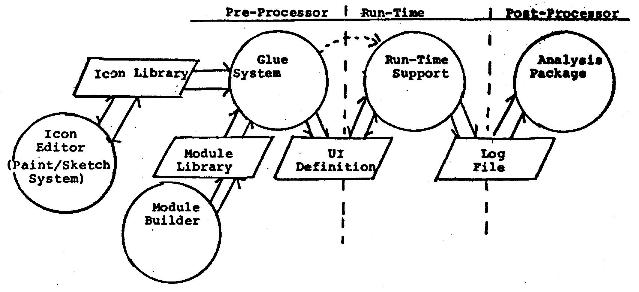
Fig. 7. Suspended-Time Modification
of UI
It is fair to assume that the interaction
programmer will often have a bias towards using existing modules from the
library, rather than going through the expense of creating new ones. This
is simply the bias of the path of least resistance. Interaction dialogues
will, therefore, be flavoured by the interaction library of the UIMS on
which they were created. This bias is something that should not be determined
by chance. Rather, it should be assumed that the system is biased, and
this bias be used to encourage preferred types of dialogue style. The problem
for the user interface manager, therefore, is to determine the appropriate
degree of generality that must be supported. As a guide, a system should
generally support implementing dialogues as diverse as, for example, the
selection positioning task described in Buxton (1982): dragging, moving-menu/stationary
cursor, character recognition, typing, or function keys.
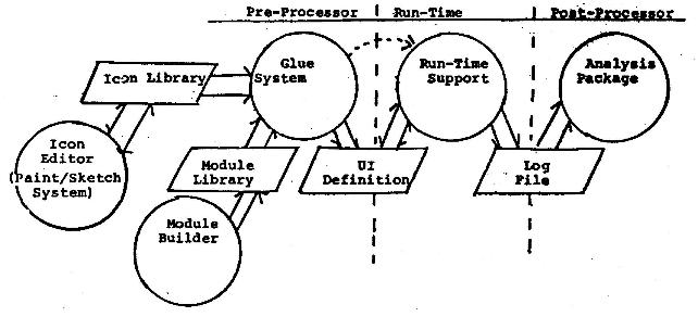
Fig. 8. UIMS model with Analysis
Module
The support given by the graphics system and the O/S is another concern. The nature of the UIMS greatly affects the type of support needed. For example, SYNGRAPH (Olsen & Dempsey 1983) looks at its input as a single stream of tokens which it then parses. When semantic feedback is required for constantly sampled input, such as that from a locator, it would be appropriate to consider changes in the locator position as events, allowing the parser to receive its tokens through an AWAIT EVENT type of mechanism. However, this use of sampled devices as event emitting devices is not permitted in GKS (International Organization for Standardization 1983). What is required is the ability to specify a new layer which enables devices to send event reports at specified time intervals or when a normally sampled device changes value by a specified amount.
Going to the opposite extreme, ACTION services each of its active dialogues once during each "tick" (see Appendix A). In this case, all the active devices are sampled to check their current status. Even buttons and changes in the tablet pen status are sampled rather than dealt with in an event driven manner. A polling UIMS needs only the GKS sample device support, and does not need event queues or triggers since event detection and event response are handled by the interaction dialogue specification. It does, however, need special device handlers that save such events as pen pushes so that they may be handled during the next tick.
GKS supports the Implementation of simultaneously active parallel input devices. Each input device may have an independent active measure process and a trigger process. However, implementing many communicating processes on most operating systems results in significant context switching and memory overhead. Similarly the external control UIMS shown in Fig. 2 (Thomas, Hamlin, et al 1982), implemented as a set of separate communicating processes, results in the same overhead problem.
An operating system design that may be very appropriate for supporting the many sequential processes of a UIMS is one that would allow fast execution of message passing between processes, rapid context switching, and low. per-process overhead. Such a system, Thoth (Gentleman 1981), has-been used for several years at the University of Waterloo. A descendant of Thoth, Harmony (Gentleman 1983a, 1983b), which supports rapid message passing among processes on a multi-processor system has recently been written at the National Research Council of Canada. Both Thoth and Harmony use a small set of message passing primitives to support inter-process communication and I/O. Message passing is very quick, taking about 1 ms for a Send-Reply-Receive sequence.
From a UIMS designer's point of view, perhaps
the most interesting experience derived from the use of such a system is
that gained from the programming of an interactive Paint program (Beach,
Beatty, Booth, Plebon & Fiume 1982; Plebon & Booth 1982). Figure
9 shows the organization chart for this multiprocess Paint program. As
we shall see, the Paint User Interface bears a certain similarity to a
UIMS. The Tablet Administrator takes the place of both the GKS active measure
process and the trigger process for the tablet.
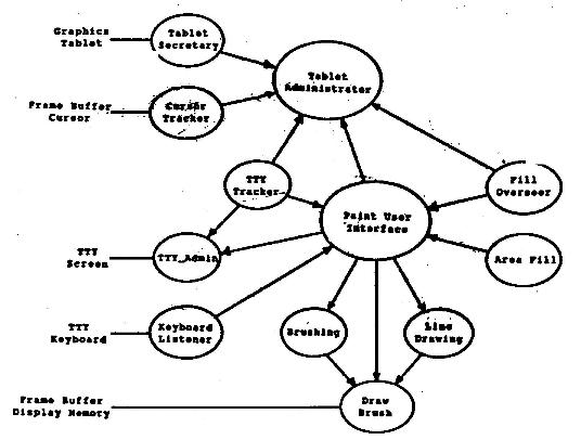
Fig. 9. Organizational Chart
for Paint Program (from Beach et al 1982)
The Paint User Interface samples tablet values which can then be sent to active application modules, such as Brushing, Line Drawing, or Draw Brush. The Tablet Administrator can reply to a request for a trigger from the Fill Overseer (if the user pushes a tablet button). The Fill Overseer is a temporary process that, on receiving a tablet trigger, will signal the Paint User Interface to abort the Area Fill process. The Tablet Administrator receives the tablet information from the Tablet Secretary, and sends the tablet X,Y position to the Cursor Tracker to update the echo. The Tablet Administrator is never blocked waiting for the completion of a message passing sequence. Processes that need information from the Administrator request it using a .Send. (After a process issues a .Send, its excution is blocked until it receives a reply.) The administrator gives the information using a nonblocking reply. Gentleman (1981) includes a good description of the organization of interactive and real time programs written with Thoth.
Using such an operating system makes it natural to program parallel processes to process parallel input. Going one step further, a Harmony-type O/S could control a multi-processor system that includes the processors that act as controllers for various devices. For example, the Tablet Administrator could be simply a process on the frame-buffer controller, passing lexical feedback messages to the display controller process with a rapid transmission speed (since the two processes are on the same processor), but passing tablet position values to the application modules on different processors at a slower speed.
This section has only touched on a few
of the issues in using message-passing operating systems to support UIMS's.
It is an approach that seems well suited for UIMS support; however, very
little of the leg work has yet been done. Much effort will have to be spent,
and many problems overcome before we will know whether these operating
systems are indeed appropriate. At this stage, we believe that experimental
implementations of UIMS's on such systems would be a worthwhile exercise.
Major problems that remain to be adequately
addressed concern how the UIMS relates to other major components of the
computing environment,* namely the operating system, graphics support utilities,
window manager, and workstation design.
Ball E, Hayes P (1982) A Test-Bed for User Interface Designs. Proceedings of the First Conference on Human Factors in Computer Systems. Gaithersburg, Maryland: 85-88.
Beach, R.J., Beatty, J.C., Booth, K.S., Plebon, D.A., Fiume, E.L. (1982). The message is the medium: Multiprocess structuring of an interactive paint program. Computer Graphics 16(3): 277-287.
Borufka HG, Kuhlmann HW, ten Hagen PJW (1982) Dialogue cells: A method for defining interactions. Computer Graphics and Applications. 2(5): 25-33.
Buxton W. A., Sniderman R. (1980). Iteration in the design of the human-computer interface. Proceedings of the 13th Annual Meeting of the Human Factors Association of Canada: 72-81.
Buxton W.A. (1982). An informal study of selection positioning tasks. Proc. Graphics Interface '82. 8th Conf. of the Canadian Man-Computer Communications Society, Toronto: 323-328.
Buxton WA (1983) Lexical and pragmatic considerations of input structure. Computer Graphics 17(1): 31-37.
Buxton W, Fiume E, Hill R, Lee, A, Woo C (1983). Continuous Hand-Gesture Driven Input. Proc. Graphics Interface '83, 9th Conference of the Canadian Man-Computer Communications Society, Edmonton: 191-195
Buxton WA, Lamb MR, Sherman D, Smith KC (1983). Towards a comprehensive user interface management system. Computer Graphics, 17(3): 31-38.
Durham I, Lamb D, Saxe J (1983) Spelling Correction in User Interfaces. Comm. ACM 26(10): 764-773.
Feldman M, Rodgers G (1982) Toward the design and development of style-independent interactive systems. Proc. 1st Annual Conference on Human Factors in Computer Systems, Gaithersburg Maryland: 1 1 1-116.
Foley J (1982) Framework for the design, evaluation, and implementation of user-computer interfaces. Proc. Graphics Interface '82, 8th Conf. of the Canadian Man-Computer Communications Society, Toronto, (abstract only): 1
Garrett MT, Foley JD (1982) Graphics Programming Using a Database System with Dependency Declarations. ACM TOG, 1(2): 1-09-128.
Gentleman WNI (1981) Message passing between sequential processes: The reply primitive and the administrator concept. Software Practice and Experience, 1 1: 435-466.
Gentleman WM (1983a) If only the hardware... (A software designer's lament). Proceedings of the IEEE International Workshop on Computer Systems Organization: 88-95
Gentleman W M (1983b) Using the Harmony Operating System. Technical Report ERB-966 NRC No. 23030, National Research Council of Canada, Ottawa.
International Organization for Standardization (1983) Information Processing-Graphical Kernel System (GKS) Functional Description, ISO/DIS 7942.
Kasik DJ (1982) A user interface management system. Computer Graphics 16(3): 99-106
Mason R, Carey T (1983) Prototyping Interactive Information Systems. Comm. ACM 26(5): 347-354.
Newman W (1968) A System for Interactive Graphical Programming. Proc. Spring Joint Computer Conference: 47-54.
Olsen DR Jr, Dempsey EP (1983) SYNGRAPH: A graphical user interface generator. Computer Graphics 17(3): 43-50
Plebon DA, Booth KS (1982) Interactive picture creation systems. CS-82-46, University of Waterloo Computer Science Department.
Roach J, Hartson R, Ehrich R, Yunten T, Johnson D (1982) DMS: A comprehensive system for managing human-computer dialogue. Proc. 1st Annual Conference on Human Factors in Computer Systems, Gaithersburg, Maryland: 102-105.
Rubel Software (1983) BLOX Graphics Builder. Rubel Software, One Soldiers Field Park 605, Cambridge, Massachusetts 02163.
Sheil B (1983) Power tools for programmers. Datamation 29(2): 131-144
Sutherland, IE (1966) Computer Graphics: Ten Unsolved Problems. Datamation 12(5): 22
Swartout W, Balzer R (1982) On the inevitable intertwining of specification and implementation. Comm. ACM 25(7): 438-440.
Tanner PP, Evans KB (1979) ACTION, a graphics aid to interacting with models and simulations. Proc. 6th Conf. of the Canadian Man-Computer Communications Society, Ottawa: 49-61.
Tanner PP (1979) ACTION, a graphics aid to interacting with models and simulations. M. Sc. Thesis, Carleton University. Available as ERB 920 from the National Research Council of Canada, Ottawa.
Tanner PP, Wein M, Evans KB (1981). Dynamic illustrative graphics for simulations. DISPLAYS Technology and Application, 2(5): 245-250.
Thomas J.J., Hamlin G.H., et al (1982) Graphical input interaction technique workshop summary. Computer Graphics 17(1): 5-30
Wasserman AI, Shewmake DT (1982) Rapid Prototyping of Interactive Information Systems. ACM Software Engineering Notes. 7(5): 171-180
Wong PCS, Reid ER (1982) FLAIR-User interface design tool. Computer Graphics 16(3): 87-98
Woodmansee, G. (1983) Visi On's Interface
Design. Byte 8(7): 1666-182.
The requirements for the ACTION environment encourage a unique style of language. As the simulation and the ACTION package can run asyncronously, one has, on one hand, a simulation executing at some speed, making available some set of parameters that change over time, while on the other hand there is a set of input devices also producing time-varying values. The language must tie pairs of these values together or connect values to graphical transformations. For example, if the switchboard program contains a statement of the sort
OILTAX=POT(1)the parameter OILTAX (perhaps in an energy model), would be tied to the value of the first potentiometer. This means that OILTAX would be reset to the current value of the first pot at some request rate, usually equivalent to the CRT frame update rate. If the program were to include the statement
POSITION_XY(CAR, TABLET)the picture segment CAR would be tied to the position of the tablet pen.
In a switchboard, at any one time, several connections are being made simultaneously. Moreover, a short time interval later, those same connections are still being made unless something has changed the mode of the system. An ACTION program defines this single state switchboard. The complete ACTION program is executed once during each "tick" (the display update rate, 50-500ms depending on the complexity of the displayed image and the model). During each tick, every link in the switchboard is checked, data is passed from input devices to the model, and the picture segments on the display are modified according to the values of the simulation variables.
We can carry this model further to make it the base for a UIMS. Interaction dialogues can also be thought of in this switchboard context. At any one time, one or more interactions are possible; perhaps the user can make a selection from a menu, grab and drag an object across the screen, as well as changing object colour using both a two-dimensional valuator for the hue and saturation and a single-dimension valuator for the lightness component.
A UIMS could be constructed in which each of these possible dialogues is a separate routine or module. Then, like the ACTION language; the routine for each currently possible interactive dialogue would be run in its entirety, around 20 times per second. In the example above, a UIMS routine for a menu, one for the dragger, a third for the 2D valuator, and a fourth for the single-dimensional valuator would be simultaneously active. The user could be moving the picture segment with the dragger while simultaneously changing colour.
The dragger routine supports an interaction
which allows the user to pick an item with the tablet puck, and drag that
item while the puck button Is depressed. It then anchors the item at its
current position when the button is released. This interaction "chunks"
several interactions into one logical sequence. Using our switchboard model,
this could be implemented with the following few lines of code:
initialize:The following definitions hold for the example:
pick_seg = 0;
on_echo(drag);run:
if pick_seg = 0
pick_seg = pick(tablet image);
else if tablet_image(status) = down
move (pick_seg, tablet_image(mouse));
else
pick seg = 0;
terminate:
off echo(drag);
This dialogue routine would be run once
per tick, as would the other currently active dialogue routines. Statements
can, of course, be added to the dialogue routines to handle information
flow to and from the application and to invoke application modules in response
to some input.
2. We distinguish between lexical and semantic feedback. The difference can be seen In the difference ",message received" and "message understood".
3. Action is a program package developed at the National Research Council of Canada for adding graphics to simulation and models (Tanner 81 Evans 1979; Tanner 1979; Tanner Wein & Evans 1981). It was not originally designed as a UIMS. However, many of Its design goats were similar to that of a UIMS, and It has recently been used as one. As ACTION was Implemented In a different manner than many UIMS's, it provides a convenient foil In comparing system designs. A short description of the ACTION package and Its use as a UIMS appears as Appendix A.
4. The Ideas that appear
In this section owe a great deal to conversations with Dave Kasik and Dan
Olsen at SIGGRAPH'83.